

Advanced Cardan Shafts Technology

Comparison between Closed Bearing Eye and Split Bearing Eye
Precision Length Compensation and Long-Life Bearing Assemblies
Operating Angle
Short Designation Key
Non-Uniform Rotational Motion of a Single Universal Joint
Double Universal Joint Arrangements for Compensating Non-Uniform Rotational Motion
Comparison between Closed Bearing Eye and Split Bearing Eye


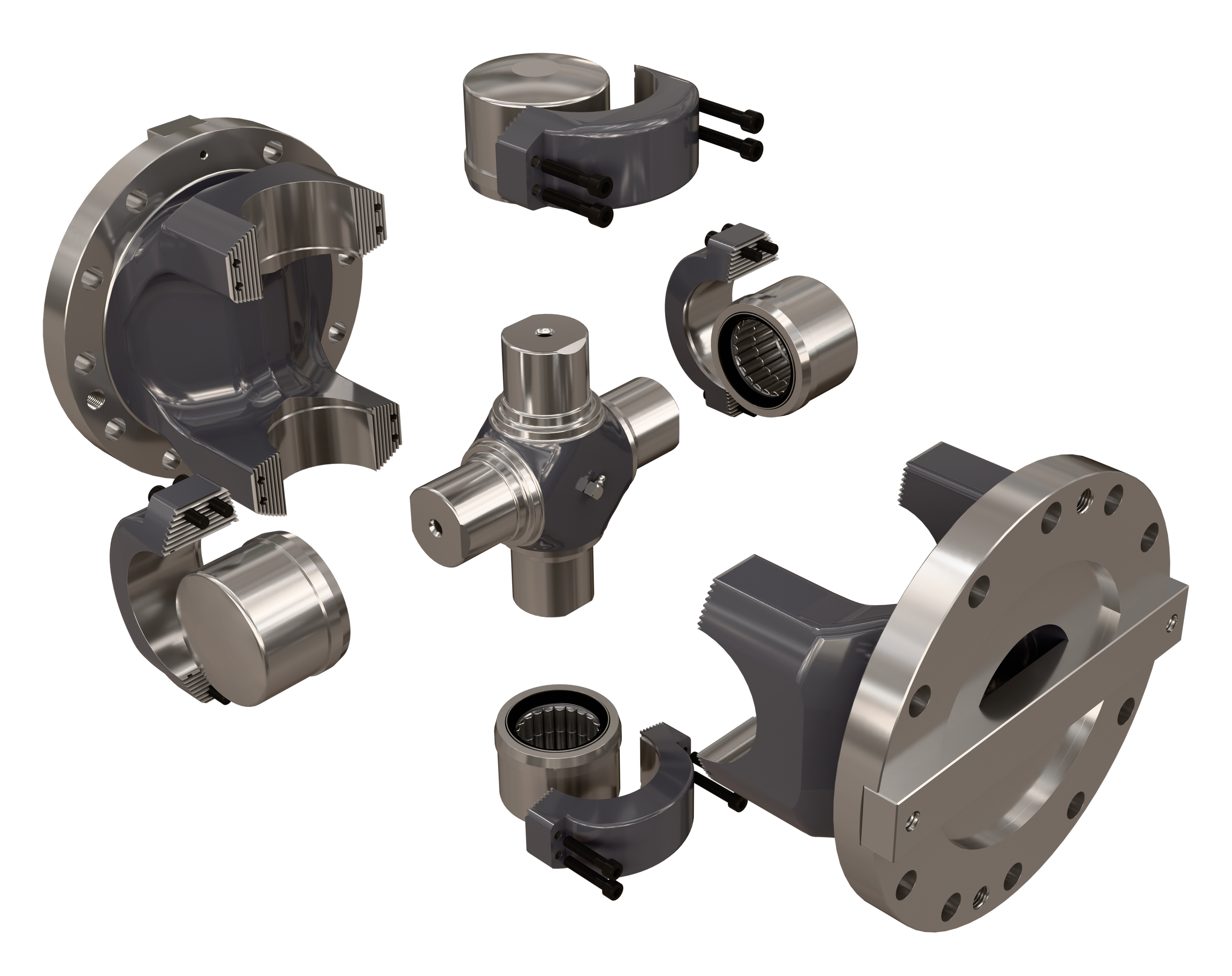
RINGSPANN Cardan Shafts are equipped with yokes featuring closed bearing eyes. Compared to cardan shafts with split bearing eyes, this design offers significant advantages in terms of service life, maintenance intervals and operational reliability:

Closed Bearing Eye


Flange yoke Closed bearing eye Yoke with bearing bore Bearing assembly Journal cross
One-piece yoke with a seamless bearing bore provides high rigidity and improved bearing support.
Only minimal deformation of the yoke and journal cross under load, resulting in improved load distribution.
No bolted connections at the bearing bore are required, which would weaken the yoke.
No bolted connections or serrations at the bearing bore that require maintenance.
The seamless bearing bore provides no entry point for corrosion.
Replacement of the journal cross assembly by a specialist workshop.
 

Split Bearing Eye


Flange yoke Bearing cap Bearing bush screws Bearing assembly Serrations Journal cross
The bearing bore is weakened by the split line in the main load zone, resulting in lower rigidity and reduced bearing support.
Increased deformation of the yoke and journal cross under load, resulting in reduced load distribution.
Bolted connections at the bearing bore require space and thus further weaken the yoke.
Bolted connections and serrations at the bearing bore require additional maintenance.
The split line at the bearing bore is susceptible to corrosion.
The journal cross assembly can be replaced on site; however, necessary subsequent tasks such as straightening or balancing can only be carried out by a specialist workshop.


Your Benefits at a Glance

  • Long service life, even under varying loads
  • Reliable operation under shock and vibration loads
  • Lower maintenance costs
  • Higher machine availability

Precision Length Compensation and Long-Life Bearing Assemblies

RINGSPANN Cardan Shafts feature sophisticated design details in every functional area. Length compensation, spline connection and bearing assem blies are carefully matched to ensure maximum operational reliability and an extended service life – even under varying loads and demanding operating conditions.


Precision Length Compensation

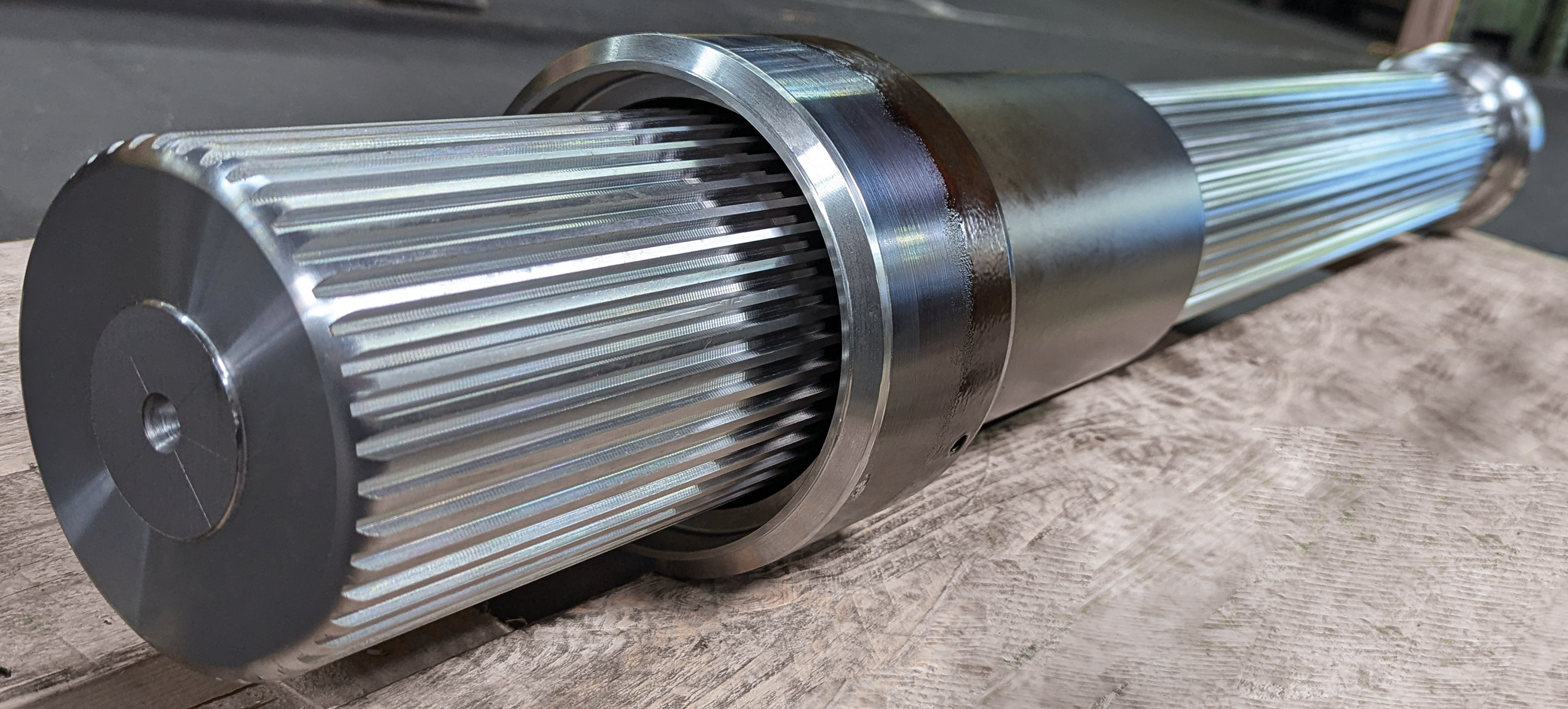
RINGSPANN length compensation systems consist of splined shafts and splined sleeves manufactured with involute splines according to DIN 5480.

Up to cardan shaft size 3070, the splines on the splined shafts are produced either by cold rolling or hobbing, while from size 3075 onwards they are manufactured exclusively by hobbing. Both manufacturing methods are characterized by low roundness and lead deviations.

Up to cardan shaft size 3070, the splined sleeves are supplied with a polymer coating as standard. This reduces friction and axial forces that arise when the splined sleeve and splined shaft are slid into one another. This offers the best possible protection, particularly for the axial bearings in the customer’s connecting assemblies. From cardan shaft size 3075 upwards, the splined sleeves are supplied gas-nitrided to withstand high loads.

Splined shafts and splined sleeves are matched to each other to further reduce the design-specified clearance.

All this results in precise and long-lasting length compensation, even under varying loads.

Hobbed splined shaft with splined sleeve in extra-long design.


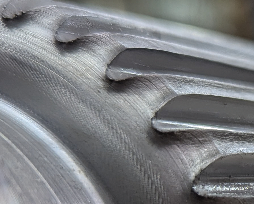
Detail view of a cold-rolled splined shafts

Cold-rolled splines are characterized by high dimensional accuracy and excellent surface quality. During the rolling process, the material’s grain structure remains uninterrupted, resulting in high strength and wear resistance. The result is uniform torque transmission at low contact pressures, with the very low surface roughness ensuring that the splined sleeve and splined shaft slide easily against one another.


Long-Life Bearing Assemblies

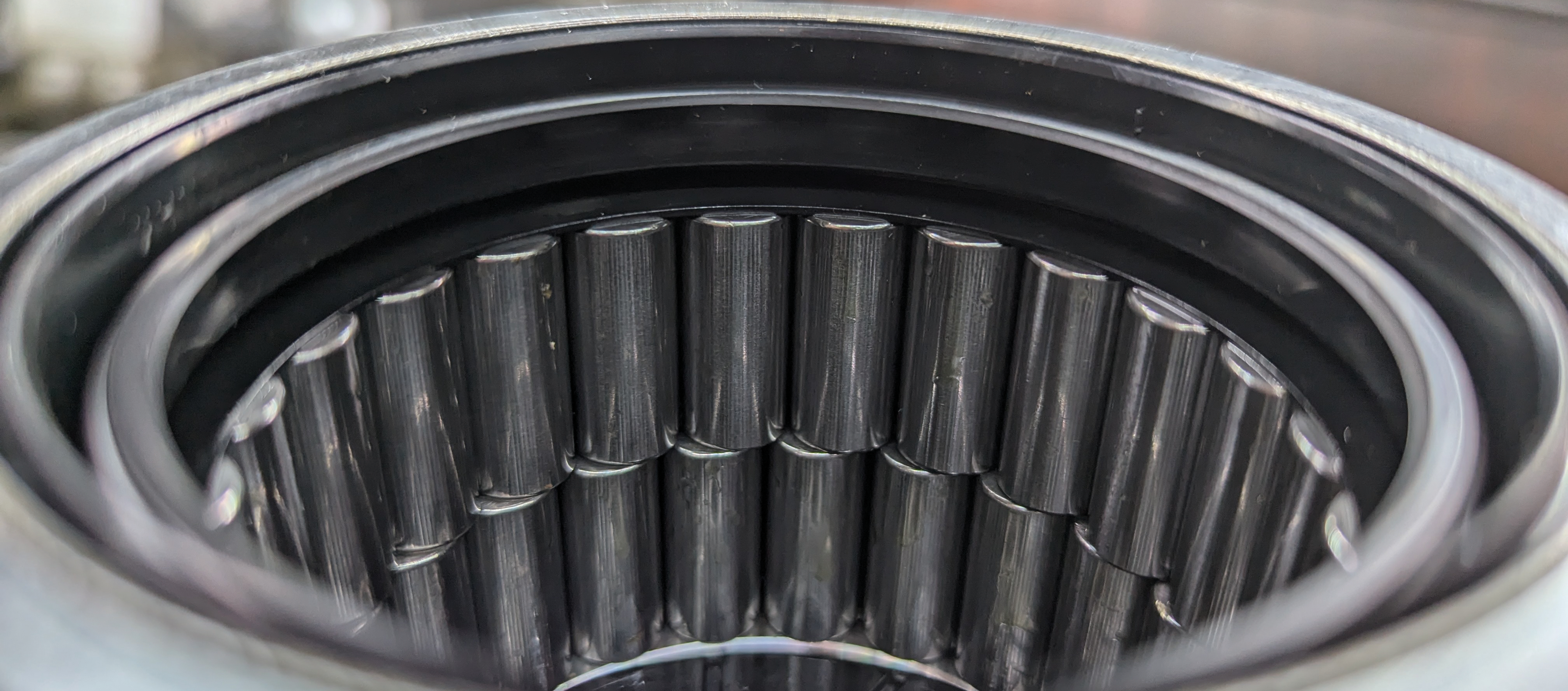
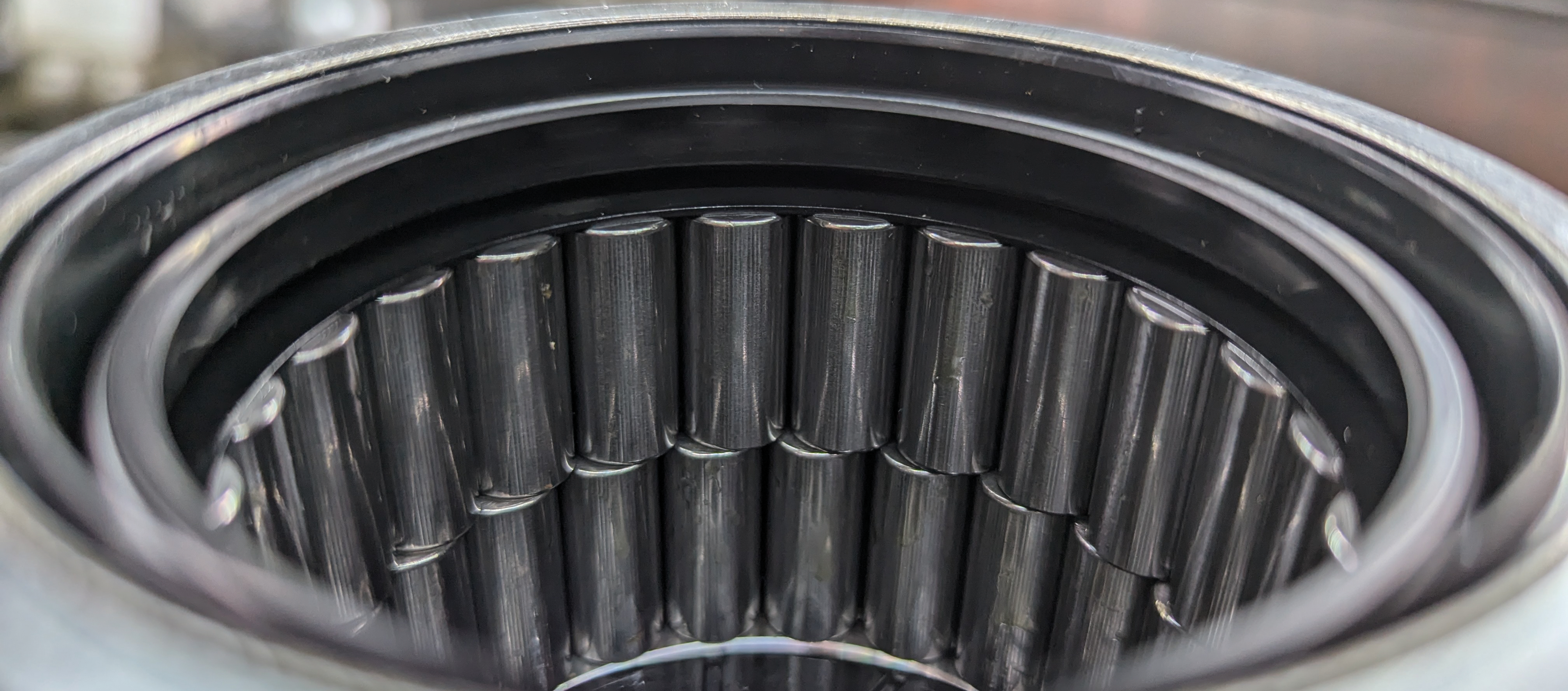
Durable and heavy-duty bearing assembly are used for the bearing support. These bearing assemblies were developed in collaboration with leading European roller bearing manufacturers. An optimized roller geometry ensures even load distribution and low friction.

The high-quality sealing system of the bearing assemblies is developed in-house and takes into account the requirements and specific characteristics of cardan shaft rolling bearings. It ensures reliable lubrication and provides long-lasting protection against the ingress of contaminants and lubricant loss.

Rolling bearing with a combined radial-axial sealing system


Your Benefits at a Glance

  • Precise length compensation during axial movements
  • Low axial forces during length compensation protect customer’s axial bearings
  • Long service life thanks to high-quality splines in the length compensation mechanism
  • Robust and long-life bearing assemblies for harsh operating conditions
  • Low wear and long maintenance intervals

Operating Angle


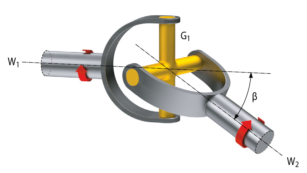
Operating Angle of a Universal Joint

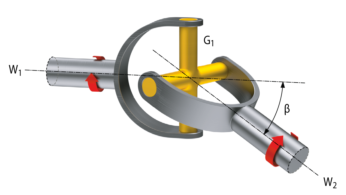
The operating angle ß of a universal joint G1 is the angle formed between the center line of the input shaft W1 and the center line of the output shaft W2.


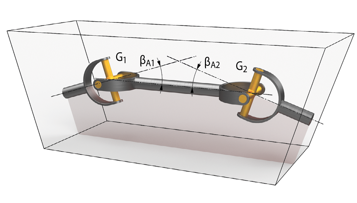
Operating Angles for Cardan Shafts

Cardan shafts have two universal joints, G1 and G2. The maximum operating angles ßA1 and ßA2 occurring at these universal joints during operation must be less than the maximum permissible operating angle ß for the selected cardan shaft size.

The maximum permissible operating angles β for each cardan shaft size are listed on pages 30, 32 and 34. In all cases, an operating angle ßA of at least 2° should be maintained.


Resulting Operating Angle

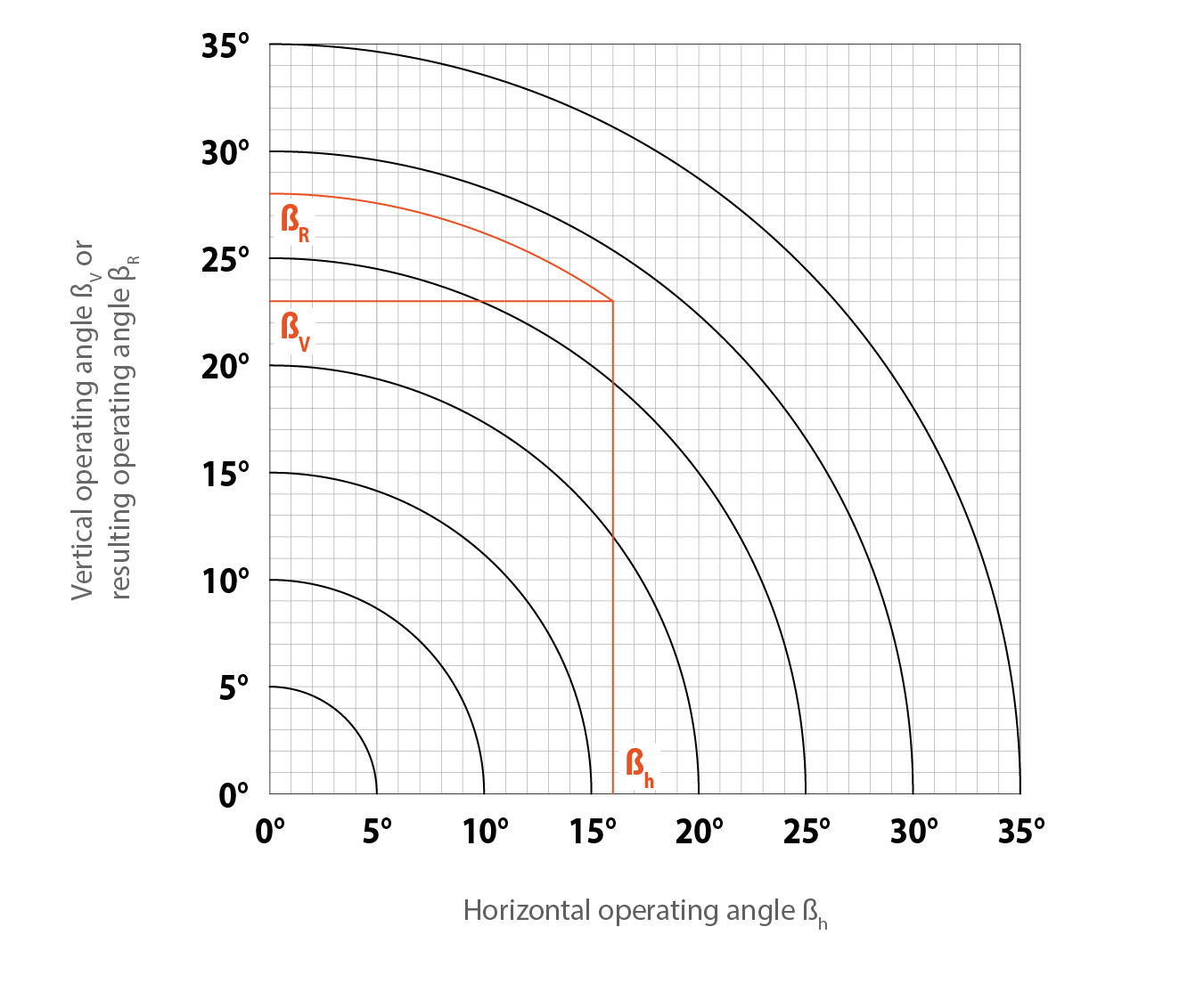
In applications involving three-dimensional deflection of universal joints, the resulting operating angle βR is the relevant parameter. It can be determined graphically from the horizontal operating angle ßh and the vertical operating angle ßv using the adjacent diagram as follows:

  • Plot the horizontal operating angle ßh on the horizontal axis and draw a vertical line from that point.
  • Plot the vertical operating angle ßv on the vertical axis and draw a horizontal line from that point.
  • Draw a radius from the origin of the diagram through the point where the vertical and horizontal lines drawn earlier intersect.
  • Read the resulting operating angle βR at the point where the radius intersects the vertical axis.

Alternatively, the resulting operating angle ßR can be calculated using the equation shown below:

ß R =arctan( tan 2 ß h + tan 2 ß v )

Short Designation Key

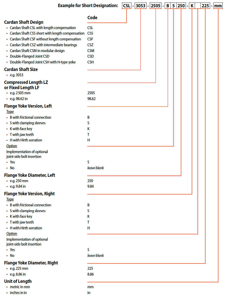
Example for Short Designation:CSL - 3053 - 2505 - BS250 - K 255 - mm

Code
Cardan Shaft Design

  • Cardan Shaft CSL with length compensation
CSL
  • Cardan Shaft CSS short with length compensation
CSS
  • Cardan Shaft CSF without length compensation
CSF
  • Cardan Shaft CSZ with intermediate bearings
CSZ
  • Cardan Shaft CSM in modular design
CSM
  • Double-Flanged Joint CSD
CSD
  • Double-Flanged Joint CSH with H-type yoke
CSH
Cardan Shaft Size

  • e.g. 3053 


Compressed Length LZ
or Fixed Length LF


  • e.g. 2 505 mm
2505
  • e.g. 98.62 in
98.62
Flange Yoke Version, Left

Type

  • B with frictional connection
B
  • S with clamping sleeves
S
  • K with face key
K
  • T with jaw teeth
T
  • H with Hirth serration
H
Option

Implementation of optional
joint-side bolt insertion


  • Yes
S
  • No
leave blank
Flange Yoke Diameter, Left

  • e.g. 250 mm
250
  • e.g. 9.84 in
9.84
Flange Yoke Version, Right

Type

  • B with frictional connection
B
  • S with clamping sleeves
S
  • K with face key
K
  • T with jaw teeth
T
  • H with Hirth serration
H
Option

Implementation of optional
joint-side bolt insertion


  • Yes
S
  • No
leave blank
Flange Yoke Diameter, Right

  • e.g. 225 mm
225
  • e.g. 8.86 in
8.86
Unit of Length

  • metric in mm
mm
  • inches in in
in

Non-Uniform Rotational Motion of a Single Universal Joint


Non-Uniform Rotational Motion of a Single Universal Joint

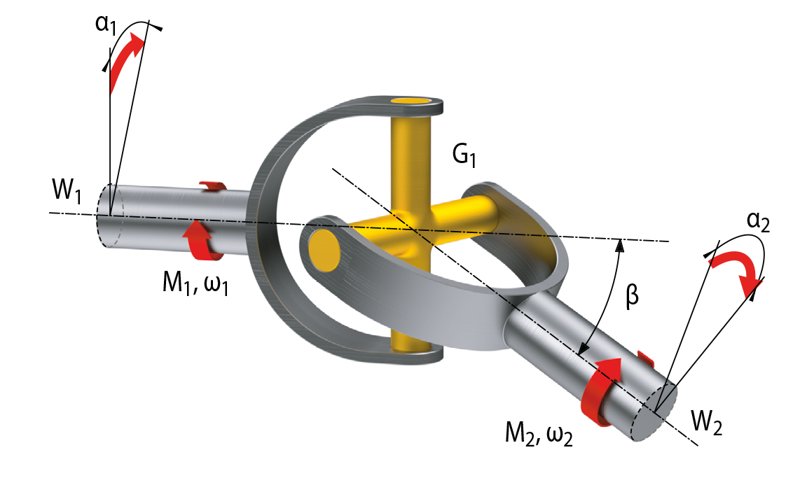
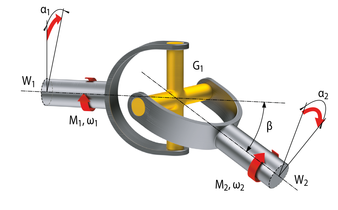
When the input shaft W1 of a universal joint rotates uniformly (angular velocity ω1 = const.), the rotation of the output shaft W2 is not uniform (angular velocity ω2 ≠ const.). Similarly, when a constant torque M1 is applied to the input shaft, the torque M2 on the output shaft is non-uniform. This characteristic behaviour of a universal joint is also referred to as cardan error and must be taken into account when selecting and designing cardan shafts.

Instructions for use:

The use of a single universal joint is suitable when:

  • the non-uniformity of the rotational motion is acceptable,
  • the non-uniformity of the torques is acceptable, and
  • the operating angle is small(typically β < 3°).

For applications with higher requirements, appropriate design measures should be considered (e.g. double-flanged joints).


Rotational Angle Difference of a Single Universal Joint

For of a single universal joint, we define the difference between the angle of rotation of the input shaft α1 and the angle of rotation of the output shaft α2 as the rotational angle difference φ = (α1 - α2).

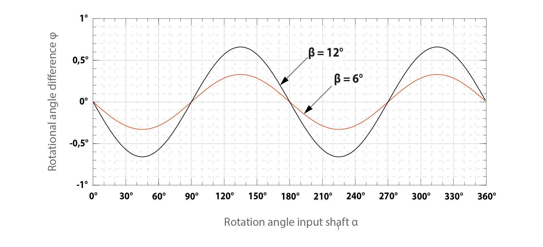
At a constant angular velocity ω1 of the input shaft, the rotational angle difference φ follows a sinusoidal curve, with the amplitude of the sine curves increasing as the operating angle β increases.

During one complete revolution of the input shaft, the rotational angle difference φ reaches maxima at rotation angles α1 of 135° and 315°, and minima at rotation angles α1 of 45° and 225°. At rotation angles α1 of 90°, 180°, 270° and 360°,the rotation angles α1 and α2 are equal, resulting in a rotation angle difference φ = 0. The following applies to the rotation angle difference:

φ = arctan  (  tan α 1 · ( cos β − 1  )  1 + cos β · tan 2 α 1  )


Angular Velocity Ratio of a Single Universal Joint

For a single universal joint, the ratio between the angular velocity ω2 of the output shaft and the angular velocity ω1 of the input shaft is referred to as the angular velocity ratio ω2/ω1.

At a constant angular velocity ω1 of the input shaft, the angular velocity ω2 of the output shaft, and therefore also the angular velocity ratio ω2/ω1, follows a sinusoidal curve. The amplitude of the sinusoidal curve increases with increasing operating angle β.

During one complete revolution of the input shaft, the angular velocity ratio ω2/ ω1 reaches maxima at angles of rotation α1 of 90° and 270°, and minima at angles of rotation α1 of 180° and 360°. At angles of rotation α1 of 45°, 135°, 225° and 315°, the angular velocities ω2 and ω1 are equal, resulting in an angular velocity ratio ω2/ω1 = 1. The following applies to the angular velocity ratio:

ω2 ω1 = cos ⁡ β 1 - sin ⁡ β 2 ⋅ sin 2 α 1


Torque Ratio of a Single Universal Joint

For of a single universal joint, the ratio between the torque of the input shaft M1 and the torque of the output shaft M2 is referred to as the torque ratio M1/M2.

The torque ratio M1/M2 corresponds to the angular velocity ratio ω2/ω1.

M1 M2 = ω2 ω1

At a constant angular velocity ω1 of the input shaft and a constant torque M1 of the input shaft, the torque M2 of the output shaft decreases as the angular velocity ω2 of the output shaft increases, and vice versa.

Double Universal Joint Arrangements for Compensating Non-Uniform Rotational Motion
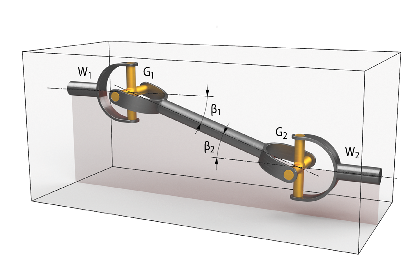
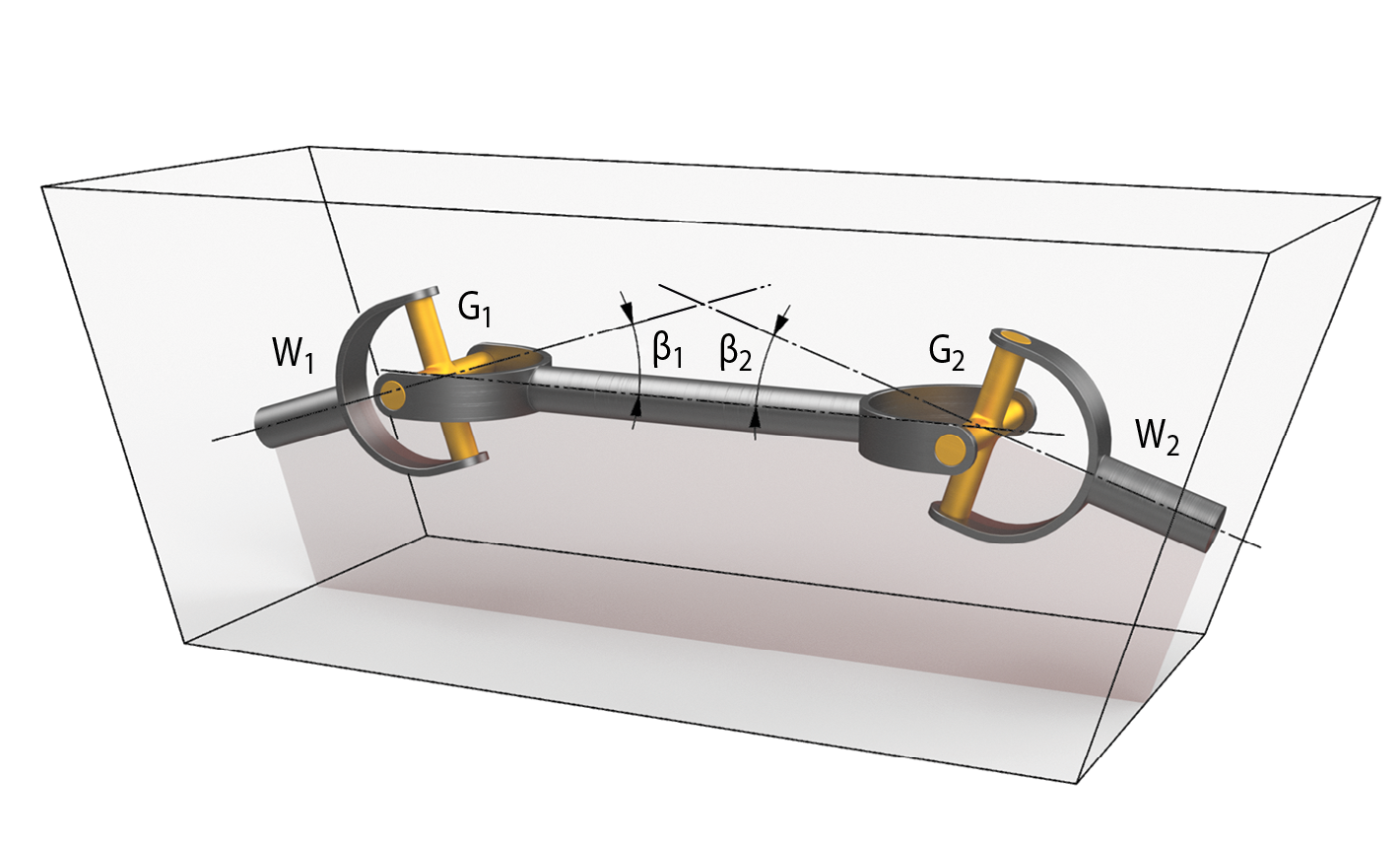
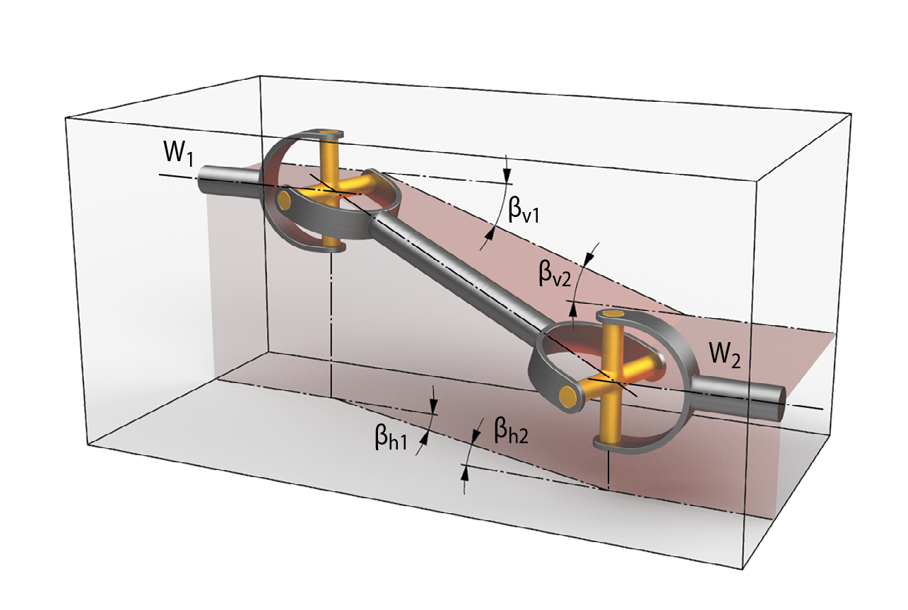
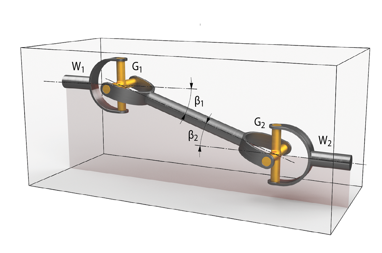
The non-uniform rotational motion of a single universal joint can be compensated by combining two universal joints into a cardan shaft. This requires both universal joints to operate at identical operating angles in a Z-arrangement, W-arrangement or 3D-Z-arrangement.

In these arrangements, the non-uniform motion introduced by the first universal joint is compensated by the second universal joint. As a result, uniform rotational motion and uniform torque transmission are achieved between the input and output shaft.

Z-Arrangement

The following conditions must be met:

  • The centerlines of the input shaft W1 and output shaft W2 of the cardan shaft must be parallel and lie in the same plane.
  • The operating angle ß1 at universal joint G1 must be equal to the operating angle ß2 at universal joint G2 sein.
    β1 = β2

W-Arrangement

The following conditions must be met:

  • The centerlines of the input shaft W1 and output shaft W2 of the cardan shaft must intersect in a common plane.
  • The operating angle β1 at universal joint G1 must be equal to the operating angle β2 at universal joint G2.
    β1 = β2

3D-Z-Arrangement

The following conditions must be met:

  • The centerlines of the input shaft W1 and output shaft W2 of the cardan shaft must lie in parallel planes.
  • The vertical operating angle ßv1 at universal joint G1 must be equal to the vertical operating angle ßv2 at universal joint G2.
    βv1 = βv2
  • The horizontal operating angle ßh1 at universal joint G1 must be equal to the horizontal operating angle ß2 at universal joint G2.
    βh1 = βh2

Contact us

Singapore


RINGSPANN Singapore Pte. Ltd.

143 Cecil Street, #17-03 GB Building

Singapore 069542

Singapore


+6012-589 8975


thinesh.kumar@ringspann.com


www.ringspann.sg

*


* *


*


*

250 / 250 characters


I accept the privacy policy *

By accepting the box you agree to receive information about our company and our news (products, catalogs ...).


✔  I am not a robot


* The fields marked with a star are required fields.